PD 500 shunt regulator triode

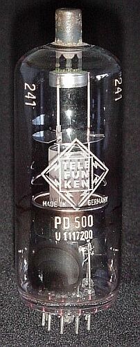
This is quite a weired tube. It was used at the beginning of the colour-TV era to stabilize the high voltage for the colour picture tubes. It was set as a shunt load in parallel to the picture tube plate and ground. During dark frames, when the picture tube didn't need much HV power, this shunt tube was opened a bit more by reducing its negative grid bias voltage. So it was adding its load to the now missing picture tube load and did provide in this way a quite constant "overall load" for the line transformer, who also produced the HV power. In this way, a dangerous increase of the plate voltage above 27.5 kV could be omitted and it could be stabilized within 25 - 27 kV. Grid bias swing was about -30 to -3 V.

It is obvious, that this is the most inefficient way to stabilize a voltage - just "heating away" the excessive power (that prior had to be generated with expensive high-power tubes such as the PL 519 and PY 500) really looks very strange today.
 

To meet these reqirements, the PD 500 was of a somewhat exotic construction: A linear electrode assembly, the cathode (0.3 A, 7.5 V) and the coaxial grid laying horizontally at the base of the tube. Both were shielded against the extremely strong electric fields by a cup-shaped cylinder (compare the HV-rectifiers 866A and 872A). The anode was made of a hollow hard-metal cylinder, supported at the top cap. Electron impact occurred only at the closed front side of this cylinder, which already was located within the shielding array - see photo. Due to the extreme acceleration of the electrons by the high voltage (25 - 27 kV), quite an intense X-radiation was generated at the plate, which often also was beginning to glow (max. load was 25 W). When looking at it against a white background, the glass bulb of the tube shown here shows a light violet colouration in the impact region, typical for longtime X-ray exposure. The hollow construction of the anode cylinder also was a means to reduce the emission of X-rays as far as possible. But despite of all this, this tube had to be built into a shielding steel case, together with the HV rectifier tube, type GY 501.